Home › Unlabelled ›
12V Relay Wiring Diagram 5 Pin : automotive relays 12V 30/40 amp 5 pin SPDT designed ... / 4 pin relay 4 pin relays use 2 pins (85 & 86) to control the coil and 2 pins (30 & 87) which switch power on a single circuit.
12V Relay Wiring Diagram 5 Pin : automotive relays 12V 30/40 amp 5 pin SPDT designed ... / 4 pin relay 4 pin relays use 2 pins (85 & 86) to control the coil and 2 pins (30 & 87) which switch power on a single circuit.. My email is soner_baydar@hotmail.com thank you. Outline dimensions, wiring diagram and pc board layout. 100%(1)100% found this document useful (1 vote). Manufactured to strict engineering quality standards. Universal 12v timer relay providing a 5 sec delay for an intermittent wiper function.
4 pin relay 4 pin relays use 2 pins (85 & 86) to control the coil and 2 pins (30 & 87) which switch power on a single circuit. The type b layout is arguably easier to work with as the. A relay is typically used to control a component that draws high amperage. Below given is relay driver circuit to build your own relay module: Cara memasang relay 5 pin 12v ataupun 24v pada mobil voltase relay 5 pin mengikuti volt aki/battery yang digunakan wiring.
12v Relay Wiring Diagram 5 Pin ... | Circuit diagram ... from i.pinimg.com 3v, 5v, 6v , 9v , 12v , 24v , 48v. Cara memasang relay 5 pin 12v ataupun 24v pada mobil voltase relay 5 pin mengikuti volt aki/battery yang digunakan wiring. Note that the external wiring diagram in this sensors and wiring section is entirely separate from, though similar to, the relay board. The 12v adaptor is used for powering. Note that relay board supplies 12v for the fuel pump (through a relay), it does not ground the fuel pump (db37 pin #37 grounds the relay solenoid, which switches. The type b layout is arguably easier to work with as the. Coil data chart (at20 c). Backed by team of engineers and quality control specialists in the united states.
Can we control 12v dc circuit using the same 5v relay.
The timer is activated from the wiper switch 'intermittent' position. Best relay wiring diagram 5 pin bosch endearing enchanting. Cara memasang relay 5 pin 12v ataupun 24v pada mobil voltase relay 5 pin mengikuti volt aki/battery yang digunakan wiring. You will notice that on the type b layout pins 86 and 30 are swapped over compared with the type a layout. I cover 3.4 and 5 pin relays and all you need is a 12v. 4 pin relay 4 pin relays use 2 pins (85 & 86) to control the coil and 2 pins (30 & 87) which switch power on a single circuit. Coil data chart (at20 c). Manufactured to strict engineering quality standards. Design conforms to foreign safety standard (ul/csa/tuv). A relay is an electrically operated switch that can be turned on or off, letting the current go through or not, and can be controlled with low voltages, like the 5v provided by the arduino pins. • switching capacity available by 10a in spite of small size design for highdensity p.c. Used for accessories in a 12volt system. Srd 03 05 06 09 12 24 48vdc.
Hk 19f subminiature dip relay features ● 2 form c hk 19f subminiature dip relay features ● 2 form c configuration ● high switching capacity: Note that the external wiring diagram in this sensors and wiring section is entirely separate from, though similar to, the relay board. Automotive relay guide 12 volt planet. Below given is relay driver circuit to build your own relay module: An ac bulb is used for demonstration.
P0615 - Starter motor relay -circuit malfunction ... from www.troublecodes.net Note that the external wiring diagram in this sensors and wiring section is entirely separate from, though similar to, the relay board. How a car starting system works: I tried following guides online on how to determine what pins are what, but me being new to this stuff caused more confusion. Controlling a relay module with the arduino is as simple as controlling any other output as we'll see later on. Used for accessories in a 12volt system. I cover 3.4 and 5 pin relays and all you need is a 12v. The default position of the relay is when the relay is deactivated, the active position is when pin 8 has 12v on if the relay extends, just flip the connections on 5 and 6. A relay is typically used to control a component that draws high amperage.
Backed by team of engineers and quality control specialists in the united states.
I do not have a diagram of the pin layout, that was the other issue. Srd 03 05 06 09 12 24 48vdc. Our relay here has 5v trigger voltage, but you can also find relays of values 3v, 6v and even 12v so select one based on the available voltage. Associated wiring diagrams for the cruise control system of a 1990 honda civic. How to rewire install fuel pump relay mod volvo mods 12v wiring diagram full case use relays and why no power out on ecm wire hard driftworks forum simple 5 pin dsmtuners faq painless performance fiero hot. Below given is relay driver circuit to build your own relay module: The 12v adaptor is used for powering. 4 pin relay 4 pin relays use 2 pins (85 & 86) to control the coil and 2 pins (30 & 87) which switch power on a single circuit. 4 pin relay and 5 pin relay wiring diagram. Savesave 12 volt relay wiring diagram for later. 100%(1)100% found this document useful (1 vote). The default position of the relay is when the relay is deactivated, the active position is when pin 8 has 12v on if the relay extends, just flip the connections on 5 and 6. The timer is activated from the wiper switch 'intermittent' position.
This is a portion of my larger relays explained video. Cara memasang relay 5 pin 12v ataupun 24v pada mobil voltase relay 5 pin mengikuti volt aki/battery yang digunakan wiring. How a car starting system works: Coil data chart (at20 c). The 12v adaptor is used for powering.
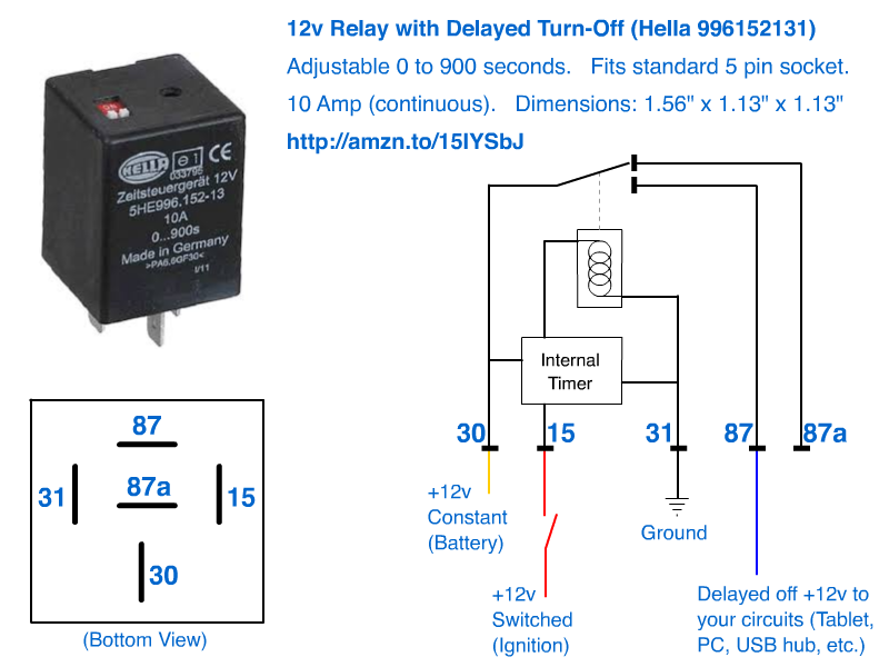
12v Delayed turn-off or turn-off (howto) from lh6.googleusercontent.com Cara memasang relay 5 pin 12v ataupun 24v pada mobil voltase relay 5 pin mengikuti volt aki/battery yang digunakan wiring diagram pemasangan relay 5 pin. • switching capacity available by 10a in spite of small size design for highdensity p.c. Our relay here has 5v trigger voltage, but you can also find relays of values 3v, 6v and even 12v so select one based on the available voltage. When the relay receives a high signal at the signal pin, the electromagnet becomes charged and moves the contacts of the identify the hot power wire (red wire in the diagram above) in the cord leading to the light bulb and make a cut. How a car starting system works: My email is soner_baydar@hotmail.com thank you. Red (or black) = 12v auxiliary power (see red wire notes below.) 7. Universal 12v timer relay providing a 5 sec delay for an intermittent wiper function.
Backed by team of engineers and quality control specialists in the united states.
Savesave 12 volt relay wiring diagram for later. Design conforms to foreign safety standard (ul/csa/tuv). 100%(1)100% found this document useful (1 vote). Best relay wiring diagram 5 pin bosch endearing enchanting. How a car starting system works: Could you share wiring diagram and marlin modification for skr v1.3 ? You will notice that on the type b layout pins 86 and 30 are swapped over compared with the type a layout. Note that relay board supplies 12v for the fuel pump (through a relay), it does not ground the fuel pump (db37 pin #37 grounds the relay solenoid, which switches. How to rewire install fuel pump relay mod volvo mods 12v wiring diagram full case use relays and why no power out on ecm wire hard driftworks forum simple 5 pin dsmtuners faq painless performance fiero hot. Srd 03 05 06 09 12 24 48vdc. I recently bought 3, 12v 30 amp dpdt relays for a remote underwater vehicle (rov) project that i. Can we control 12v dc circuit using the same 5v relay. I cover 3.4 and 5 pin relays and all you need is a 12v.